Metal Garages
June 11, 2026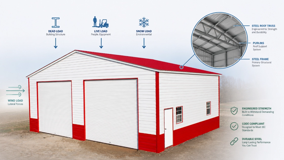
Here’s a conversation that happens more than it should: a property owner buys a steel barn, gets a great deal, and two winters later calls a structural engineer because the roof is deflecting under snow load. The building wasn’t designed for the actual conditions of the site. It was designed to be affordable.
Most buyers shopping for a metal barn, RV garage, horse shelter, or agricultural building spend the majority of their time on two things: size and price. Both matter. But the structural engineering behind the building — specifically how it handles the various loads it will carry over its entire service life — is what actually determines whether that building is still standing, and still safe, in year 30.
This guide explains engineering in plain English. You don’t need a structural engineering degree to understand the concepts that should be driving your buying decision. You need to know what questions to ask and what the answers should look like.
When an engineer talks about “load,” they’re talking about any force that the building structure must carry and transfer safely to the foundation. Every steel barn is carrying multiple types of load simultaneously at all times — even an empty building in calm weather.
Loads are measured in pounds per square foot (PSF) — the weight per unit of roof or floor area that the structural system must support. The engineering process involves calculating every load that will ever act on the building, combining them using established safety factors, and designing the framing system to handle the combined result.
The primary load types a steel barn must be designed for:
The governing standard for all of these in the United States is ASCE 7 — Minimum Design Loads and Associated Criteria for Buildings and Other Structures, published by the American Society of Civil Engineers. Every state building code references ASCE 7 as its structural foundation, which is why the specific load requirements vary by location rather than being a single national number.
Dead load is the weight of the building itself. Everything that’s permanently part of the structure contributes to the dead load: the primary frames, secondary framing (purlins and girts), roof and wall panels, fasteners, trim, doors, and any fixed built-in components.
Typical dead load values for pre-engineered steel buildings:
| Component | Typical Weight (PSF) |
| Steel roof panels (26-gauge) | 1.5–2.5 PSF |
| Steel wall panels (26-gauge) | 1.5–2.5 PSF |
| Primary steel framing (rigid frames) | 2.0–4.0 PSF |
| Secondary framing (purlins, girts) | 1.0–2.0 PSF |
| Total building dead load (typical) | 3–5 PSF |
For a standard pre-engineered steel barn with no insulation, no ceiling liner, and no HVAC equipment, total dead load typically runs 3–5 PSF. That’s the baseline the structural engineer uses for the building.
Where dead load calculations go wrong:
Dead load problems almost always come from two sources. The first is under-specifying fixed attached items — not accounting for insulation, ceiling liner panels, or utility conduit that will be added to the structure. The second, and more expensive, is adding these items after the building is built without verifying the original framing can handle them.
A spray foam insulation package on a 40×60 barn adds roughly 0.5–1.5 PSF of dead load to the roof structure, depending on thickness. Rigid foam board adds 0.3–0.8 PSF. A ceiling liner panel system adds 1.0–2.5 PSF. None of these are structurally significant in isolation — but if the original framing was specified without accounting for them, they reduce your safety margin in a way you can’t see until something deflects.
Live load is everything the building carries that isn’t permanently attached to it. The most common sources of roof live load in a steel barn context:
Roof live load covers maintenance personnel and equipment on the roof during installation, cleaning, or repairs. IBC and ASCE 7 minimum roof live load requirements are typically 12–20 PSF for low-slope roofs, but the actual value required depends on the roof slope and the tributary area of each framing member.
Floor live load in a barn context covers any activities on the floor — vehicles, equipment, stored materials, livestock. These are typically much higher loads than roof live loads. ASCE 7 specifies 50 PSF minimum for light storage, 125 PSF for heavy storage, and 250 PSF for manufacturing occupancies.
Collateral load is worth understanding separately, even though some codes treat it alongside dead load. Collateral load covers permanent but non-structural items attached to the building: HVAC systems, lighting fixtures, electrical conduit, fire suppression piping, sprinkler heads, and insulation systems. For an agricultural barn, typical collateral load runs 1–5 PSF depending on what’s installed.
Real-world scenario: the horse barn that wasn’t sized for hay storage
A horse barn owner in central Kentucky built a 36×60 steel barn with a standard 3 PSF dead load spec. After the building was erected, they used the rear third of the barn floor for hay bale storage — stacked 6 feet high. A single 4×4 hay bale weighs roughly 50 lbs; a 6-foot stack on an 8×8-foot floor area represents roughly 225 PSF of floor load. The concrete slab handled it. But the point stands: if the barn had a mezzanine or loft level instead of a concrete floor, that load calculation would have mattered enormously.
Design the building for how you’ll actually use it — including the uses you’re planning for in year 3 or year 5, not just day one.
|
Factor |
Dead Load |
Live Load |
|
Definition |
Permanent weight of structural components | Temporary or variable forces from occupancy and use |
| Examples | Steel framing, panels, fasteners, insulation | Maintenance crew, equipment, stored materials |
| Changes over time? | Only if structural modifications are made | Yes — varies constantly based on use |
| Predictability | High — can be calculated precisely from material specs | Variable — estimated from code tables based on occupancy type |
| Measured in | PSF (pounds per square foot) | PSF (pounds per square foot) |
| ASCE 7 treatment | Chapter 3 (Permanent Loads) | Chapter 4 (Live Loads) |
| Typical range for steel barns | 3–8 PSF total | 12–20 PSF (roof); 50–250 PSF (floor) |
| Most common mistake | Not accounting for future add-ons | Under-sizing for actual intended use |
| Impact on framing | Determines minimum frame size | Combined with dead load for total design load |
| Permit implication | Must be documented in structural drawings |
Must be specified for each occupancy zone |
Snow load is the single most under-specified structural factor in the U.S. metal building market — and it’s the one most likely to cause a roof failure when it goes wrong.
The ASCE 7 ground snow load (pg) is the 50-year return period snow load for your specific location — the weight of snow on level ground that has roughly a 2% chance of being exceeded in any given year. Roof snow load (ps) is calculated from the ground snow load using adjustment factors for:
For a standard unheated agricultural barn in an open, exposed location: ps ≈ 0.7 × Ce × Ct × I × pg
Ground Snow Load by Region: Practical Reference
| State / Region | Typical Ground Snow Load (PSF) | Notes |
| Florida, Gulf Coast, South Texas | 0 PSF | No design snow load required |
| Southern Plains (KS, OK southern) | 10–20 PSF | Low but non-zero |
| Carolinas, Georgia | 10–220–35 PSF 5 PSF | Varies significantly by elevation |
| Mid-Atlantic (VA, MD, PA south) | 20–35 PSF | Urban areas toward lower end |
| Midwest (OH, IN, IL, MO) | 20–40 PSF | North increases substantially |
| Upper Midwest (MN, WI, MI, ND, SD) | 40–60 PSF | Significant — don’t cut corners |
| New England (ME, NH, VT, NY north) | 50–80+ PSF | Mountain terrain can reach 100+ PSF |
| Colorado / Rocky Mountains | 50–150+ PSF | Highly elevation-dependent |
| Pacific Northwest (WA, OR mountain) | 50–100+ PSF | Cascades receive extreme loads |
| Alaska | 50–300+ PSF | Some locations extreme |
Why a 30 PSF and 60 PSF barn are structurally very different buildings:
A barn engineered for 30 PSF snow load uses framing members sized for that load, at specified spans and spacings. A barn engineered for 60 PSF snow load requires substantially heavier primary frame members, closer purlin spacing (the secondary framing that carries load to the primary frames), and heavier connection hardware throughout.
You cannot simply add a 60 PSF snow load to a building designed for 30 PSF by adding more purlins after the fact. The primary rigid frames — the tapered I-beams that carry the load to the foundation — are sized for the original specification. Exceeding that specification puts load into a frame that wasn’t designed for it.
Wind load is fundamentally different from gravity loads (dead, live, snow) because it acts horizontally and creates suction as well as pressure. A wind event doesn’t just push on the windward wall — it simultaneously pulls on the leeward wall and generates uplift on the roof that tries to separate the panels from the framing.
ASCE 7 establishes basic wind speeds for every location in the U.S. based on the 700-year return period (approximately 0.15% annual exceedance probability for Risk Category II structures). The design wind pressure on a building surface is calculated from the basic wind speed, adjusted for:
| Region | Basic Wind Speed (ASCE 7, Risk Category II) | Certification Typically Required |
| Inland Southeast, Plains, interior South | 115–130 MPH | 140 MPH building certification |
| Coastal Southeast, Gulf Coast | 140–165 MPH | 170 MPH certification |
| Florida coastal (non-HVHZ) | 150–170 MPH | 170 MPH certification |
| Florida HVHZ (Miami-Dade, Broward) | 180+ MPH | 180 MPH + Miami-Dade NOA |
| Great Plains tornado regions | 115–130 MPH (sustained) | 140 MPH baseline; tornadoes exceed any rated building |
| Pacific Coast | 110–125 MPH | 140 MPH typically |
| Hawaii | 130–180 MPH | Varies by island and elevation |
Garage doors are the largest opening on most steel barns and garages — and in a high-wind event, they’re the most vulnerable component. When a garage door fails under wind pressure, internal pressurization occurs: wind enters the building and pushes outward on the roof and walls from inside while negative pressure continues pulling the roof upward from outside. The structure experiences combined loading from both directions simultaneously, which it was not designed for.
This is why FEMA identifies garage door failure as the starting point for approximately 90% of residential wind damage in major hurricane events. In a horse barn or agricultural building with large equipment doors, the same physics apply. Wind-rated doors are not an optional upgrade in coastal and high-wind regions — they’re a structural necessity.
In steel barns and metal buildings, truss engineering refers to the design of the primary structural frames (rigid frames or trussed rafters) that span the full width of the building without interior columns. Truss engineering determines the building’s clear-span capability, load-carrying capacity, and deflection behavior under combined gravity and lateral loads.
When buyers compare metal buildings, the conversation typically gravitates toward steel gauge. “Is it 14-gauge or 12-gauge?” It’s a reasonable question, but it misses the more important structural consideration: the geometry and design of the primary framing system.
What gauge actually determines: Steel gauge measures the thickness of the steel material. Thicker steel (lower gauge number) has more cross-sectional area, which means greater resistance to bending and yielding. 12-gauge framing is approximately 40% thicker than 14-gauge and provides meaningfully more structural capacity per member.
What truss design actually determines: The truss or rigid frame is the load-carrying system that spans the width of the building. Its capacity depends on:
A shallow, lightly flanged rigid frame in 12-gauge steel may actually carry less load than a properly depth-optimized frame in 14-gauge steel, depending on the span. The combination of material specification and frame geometry is what determines structural capacity — not gauge alone.
The clear-span question:
Pre-engineered steel barns achieve clear spans — full interior width without columns — through rigid frame design. As span increases, the required frame depth increases to maintain acceptable deflection ratios. A 40-foot clear span requires a deeper frame than a 24-foot span. A 60-foot clear span requires even more depth. If a manufacturer is offering a 60-foot clear-span barn at a price point significantly below competitors, the question to ask is whether the frame geometry is adequate for the specified loads — not just whether it technically spans the distance.
Frame spacing and its effect on load distribution:
Standard frame spacing in pre-engineered buildings is typically 5 feet on center for residential applications. High-load applications — heavy snow loads, wind-certified structures — often use 4-foot frame spacing, which distributes roof loads across more primary frames and reduces the demand on each individual frame. This costs more (more frames per linear foot of building) but produces meaningfully better structural performance in demanding climates.
This section covers one of the most expensive mistakes a metal building buyer can make: ordering a building to minimum specifications and then adding load-bearing upgrades after the fact without engineering review.
Rooftop solar on agricultural and commercial metal buildings is growing rapidly. A standard solar panel installation adds 3–6 PSF of dead load to the roof. Racking hardware, wiring, and conduit add another 0.5–1.5 PSF. Total additional dead load from a rooftop solar system: 4–8 PSF.
For a building specified to minimum dead load with tight safety margins, this addition may exceed the original design capacity. Solar installations on metal buildings require engineering review of the existing structure before installation — and in many cases require modifications to the purlin system or additional intermediate framing.
If you have any intention of adding solar in the next 10 years, specify a collateral load allowance of at least 5–8 PSF in your original building order. The cost difference in the original construction is minimal; the cost of structural modification after the fact is not.
Closed-cell spray foam insulation is an excellent choice for agricultural and commercial metal buildings — excellent temperature control, condensation prevention, and air sealing. It also adds dead load.
Typical closed-cell spray foam at 2-inch thickness: 0.6–1.0 PSF At 3-inch thickness: 0.9–1.5 PSF Full coverage walls and roof: 1.0–2.0 PSF additional dead load
This is generally within standard dead load specifications for most buildings. However, for buildings in high-snow-load regions where the structure is already working at elevated loads, the additional dead load from insulation reduces the margin available for design loads. Specify collateral load accordingly.
Commercial rooftop HVAC units are heavy. A 3-ton rooftop unit weighs 250–350 lbs; a 5-ton unit weighs 400–600 lbs. These loads are concentrated at specific framing locations rather than distributed across the roof surface — which means the individual purlin and frame supporting the unit must be checked for the point load, not just the average PSF across the roof.
For any metal building where rooftop HVAC is planned, the unit location and weight must be specified to the structural engineer at the design stage. After-the-fact HVAC unit placement on an unreviewed building is a structural risk.
Steel liner panel systems on the interior ceiling add 1.0–2.5 PSF of dead load to the roof structure. They’re popular in commercial and workshop applications for appearance and to improve insulation performance. Specify them in the original order — retrofitting a liner system requires verifying the purlin capacity for the additional dead load.
The engineering considerations in this guide aren’t designed to make buying a metal building complicated. They’re designed to help you ask the right questions — so you end up with a building that performs the way it should for the next 40 years, not one that performs adequately until the first major weather event.
Viking Metal Garages provides engineer-certified structural drawings with most enclosed building orders — drawings that are specified to your county’s actual ASCE 7 wind and snow load requirements, produced by licensed structural engineers. Our building specialists ask for your zip code at the start of every design conversation because the right building for your location depends on numbers that vary by county, not by state or by region.
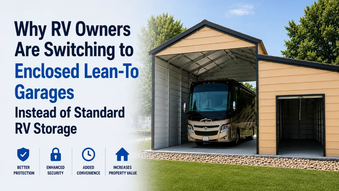
Explore our full range of metal barns, horse barns, agricultural buildings, and commercial steel structures — or explore RV garages and custom metal garages sized to your vehicles and site.
Call (704)-741-1587 to talk through the engineering requirements for your specific location and use case, or request a free quote online. Getting the structural specification right from the start is the most important decision you’ll make — and it’s one our building specialists handle for customers across all 48 contiguous states every day.
Expand each item below to explore a few helpful answers before moving to the next blog post.
The answer should reference your county's ASCE 7 design wind speed — not a generic "our buildings are 140 MPH rated." The certification should be specific to your building and your location.
Same specificity required. A building engineered for 30 PSF ground snow load is not the right building for a site in northern Minnesota where the requirement may be 50–60 PSF.
Get a number. If the answer is 3 PSF and you're planning to add insulation, ceiling liner panels, and rooftop solar later, that 3 PSF specification will not accommodate your plans.
Collateral load covers HVAC, insulation, lighting, and other permanently attached non-structural items. A standard collateral load allowance in the specification is typically 1–3 PSF. If your building use requires more, specify it.
Standard is 5 feet; high-load applications use 4 feet. This matters for snow and wind performance.
The drawings should be produced by a licensed structural engineer registered in your state, and they should specify the design loads used. Your county building department will check this.
14-gauge is standard for most residential applications; 12-gauge is required for high-wind and high-snow certifications. Know what you're getting.
A building designed for easy end-wall extension has different end-frame specifications than one that isn't. If expansion is planned, specify it upfront.